MC Simulation
This section explain the example of the Monte Carlo simulation by using artemis.
This section explain the example of the Monte Carlo simulation by using artemis.
It is very useful to use Monte Carlo (MC) simulation to obtain various calculated values. From this section, we will show the simple example how to perform MC simulation using artemis.
First, we will set the generator of the beam that will bombard on the target. We have two kinds of generator:
After you get beam information from a measurement, second option might be useful.
This is an example of a steering file.
Processor:
  - name: random_eventstore
    type: art::TRandomNumberEventStore
    parameter:
      OutputTransparency: 1
      MaxLoop: *loopnum

  - name: beam_generator
    type: art::TRandomBeamGenerator
    parameter:
      OutputCollection: *beam_name
      OutputTrackCollection: *track_name
      #beam particle information
      MassNum: *beam_A
      AtomicNum: *beam_Z
      ChargeNum: *beam_Z
      IniEnergy: *beam_E
      #beam tracking information
      Xsigma: 1.0 # mm
      Ysigma: 1.0 # mm
      Asigma: 1.0 # deg
      Bsigma: 1.0 # deg
      Esigma: *beam_Esigma
This produces two branch, “beam” and “track”.
Actually “track” information is contained in “beam” branch.
Here is the detail of the type of “beam”.
artemis [] classinfo art::TParticleInfo

 art::TParticleInfo

 Data Members

                      int   fMassNumber
                      int   fAtomicNumber
                      int   fCharge
                   double   fEnergy                kinetic energy in LAB system
                   double   fCurrentZ              current Z position
                   double   fTime                  Duration time (ns)
                   TTrack   fTrack                 tracking information in LAB system
           TLorentzVector   fVec                   lorentz vector (px, py, pz, E) of this particle
                   double   fTheta_cm              theta angle (deg) in CM system
                   double   fPhi_cm                phi angle (deg) in CM system

-- snip --
fCurrentZ is the current Z position and at the beam generation, this value will be set as 0 after this processor.
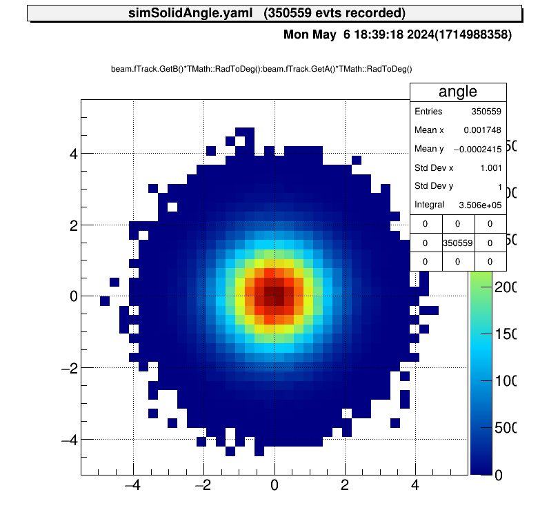
For example, the beam angle distribution will be like this.
The tracking information obtained from the experiment can also be used to generate the beam. In the current version, the position and angle of the beam are read from a ROOT file and the energy is given randomly.
This is an example of a steering file.
Processor:

  - name: periodic_tree
    type: art::TTreePeriodicEventStore
    parameter:
      OutputTransparency: 1
      FileName: *input
      TreeName: tree
      MaxEventNum: *loopnum

  - name: proc_copy_processor
    type: art::TBranchCopyProcessor
    parameter:
      InputCollection: f3ppac # need to inherit from TTrack
      OutputCollection: *track_name

  - name: beam_generator
    type: art::TTreeBeamGenerator
    parameter:
      InputCollection: *track_name
      OutputCollection: *beam_name
      # beam particle information
      MassNum: *beam_A
      AtomicNum: *beam_Z
      ChargeNum: *beam_Z
      IniEnergy: *beam_E
      Esigma: *beam_Esigma
It reads an object named “f3ppac”, which inherits from TTrack, from a TTree named “tree” in a file named “*input”,
and creates an object of the same type as before named TParticleInfo.
make a reaction considering phase space.
  - name: reaction_proc
    type: art::TNBodyReactionProcessor
    parameter:
      InputCollection: *beam_name
      OutputCollection: products # size is DecayParticleNum
      OutputReactionCollection: reaction
      # beam information (for initialize TSrim)
      BeamNucleus: [*beam_Z, *beam_A] # (Z, A)
      BeamEnergy: *beam_E
      # target information
      TargetIsGas: true # false-> solid, true-> gas target
      TargetName: he # from TSrim energy loss
      TargetMassNum: 4 # hit ion
      TargetAtomicNum: 2 # hit ion
      TargetThickness: 1000 # mm (for gas target, allow up to this value)
      TargetPressure: 250 # Torr (used for gas target)
      # reaction particles information
      DecayParticleNum: 2
      ReactionMassNum: [29, 1] # will be [id=0, id=1]
      ReactionAtomicNum: [15, 1]
      ExciteLevel: [0.0, 0.0] # MeV
      # cross section file, if not, it use constant cross section for energy
      # require: "energy cross-section" format, deliminator should be a space ' '
      CrossSectionPath: path/to/cs/file
      CrossSectionType: 0 # 0-> LAB, kinematics is different, 1-> LAB, kinematics is same, 2-> CM
NOTE
TargetName that registered this library# comment
# energy cross_section
0.0 0.0
0.1 1.0 # comment
# 0.2, 2.0 camma is not allowed...products is size two array, like products[0] -> id=0 particlereaction contain reaction information, like Ecm, Thetacmartemis [] classinfo art::TReactionInfo
art::TReactionInfo
Data Members
double fEnergy / Ecm of the reaction
double fTheta / Thetacm of the reaction
double fX / reaction position at LAB system, x
double fY / reaction position at LAB system, y
double fZ / reaction position at LAB system, z
double fExEnergy / excited energy of residual nucleus
ESortType kID
ESortType kTiming
ESortOrder kASC
ESortOrder kDESC We will show an example of a simulation performed for a gas target case like the steering file above. (of course we can use it also for solid target case!)
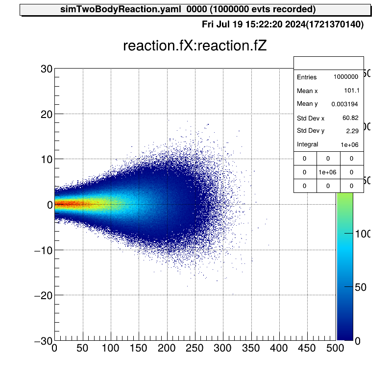
Details of the reactions that took place are shown in these figures.
The reaction cross section files are appropriately specified.
This figure is the reaction energy at CM system.
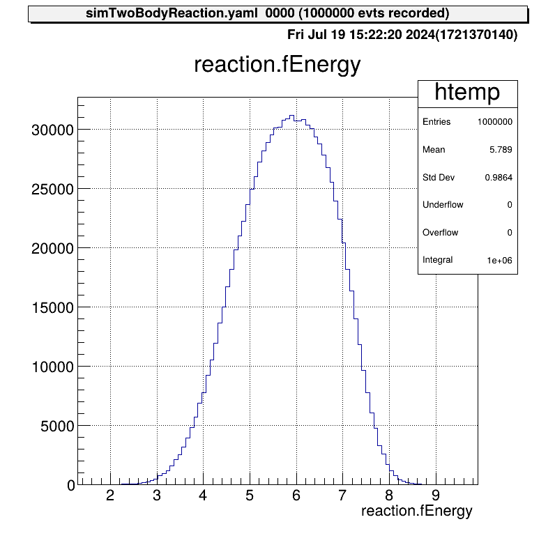
This distribution was created from a file of reaction cross section. The effect of beam energy spread is included, so the edge of the peak is not sharp.
According to this energy distribution, the distribution of the positions of the reactions is as follows.
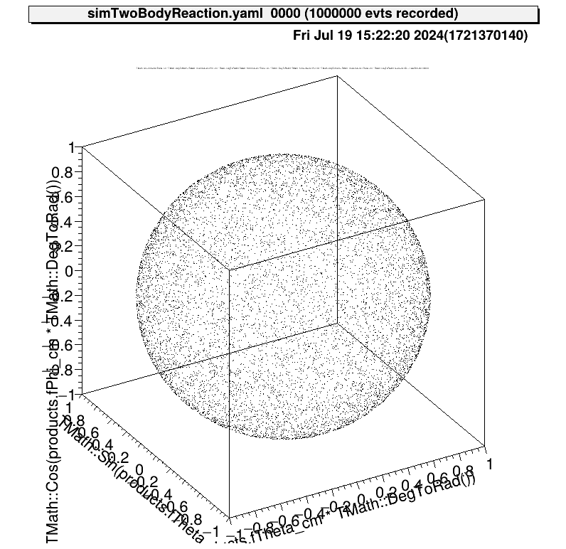
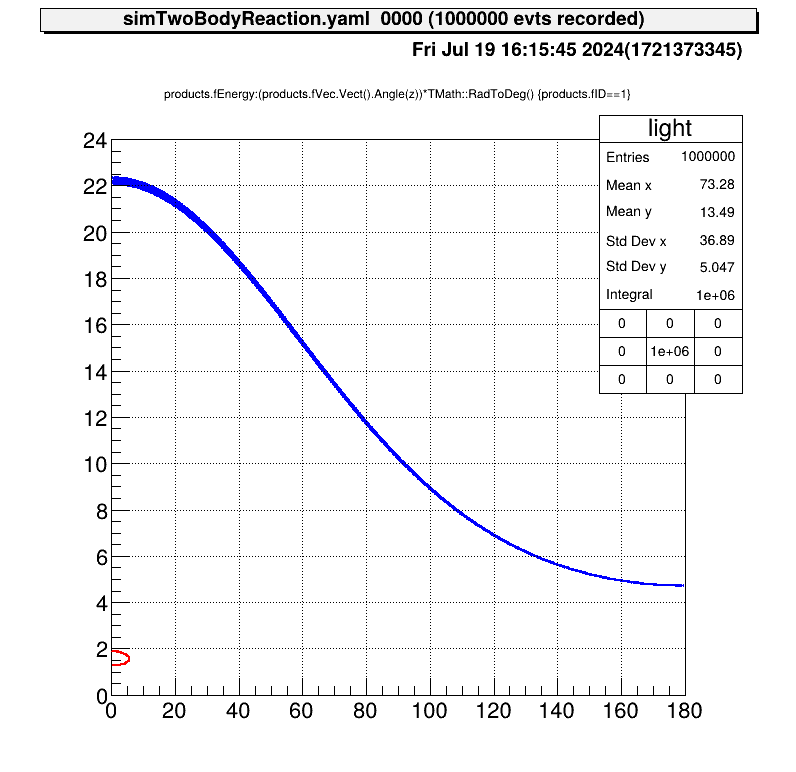
The angular distribution at CM system of reactions is assumed to be uniform. This figure shows the direction of one particle that is produced from this reaction.
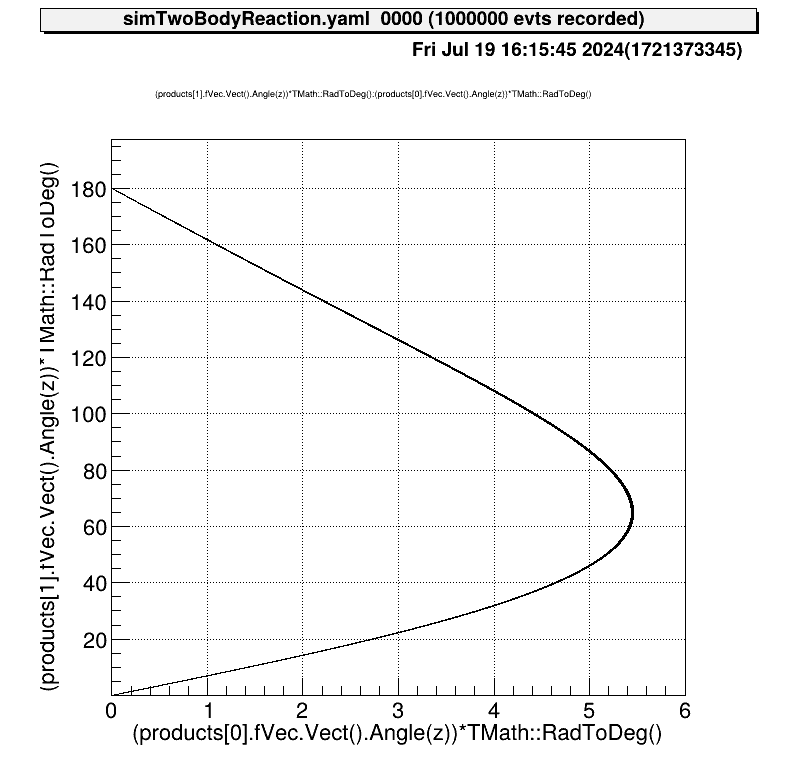
Also the relationship between the kinematics of the reactions will be like this.
Configure detector geometry to judge if the reaction particle hit the detector or not.
material:
  - name: Vaccum # id=0
    atomic_mass: 0.0
    atomic_num: 0.0
    density: 0.0 # g/cm3

  - name: Si # id=1
    atomic_mass: 28.084
    atomic_num: 14.0
    density: 2.321

# Note: beam axis -> z, upper direction -> y
conposition:
  detector:
    - name: tel1
      strip: [16, 16]
      center_rotation: [0., 0., 322.0] # mm
      offset: [0., 0., 0.]
      distance: 244.0
      angle: -4.0 # deg
      thickness: [0.02, 0.301, 1.494, 1.486]
      pedestal: [0., 0., 0., 0.] # MeV, below this energy, assume 0 MeV
      material: [Si]

    - name: tel2
      strip: [16, 16]
      center_rotation: [0., 0., 322.0]
      offset: [0., 0., 0.]
      distance: 154.5
      angle: 27.0
      thickness: [0.02, 0.300, 1.494, 1.485]
      pedestal: [0., 0., 0., 0.] # MeV, below this energy, assume 0 MeV
      material: [Si]

volume:
  top: # detector world
    name: TOP
    type: box # now only box is available
    material: 0
    size: [400.0, 200.0, 1288.0] # mm

  detector:
    - name: tel1
      type: box
      material: 1
      size: [50.0, 50.0, 1.0] # mm

    - name: tel2
      type: box
      material: 1
      size: [50.0, 50.0, 1.0] # mm
The geometry information is used only for the judgement, so any material is actually okay.
The material node is used to define TGeoMaterial and TGeoMedium classes.
From name to density node are used to make a instance of this object.
This values are not used in the current processors.
The next conposition node define the detector configuration.
General telescopes of the CRIB experiment consist of DSSSD and SSD (single-pad),
and the node below defines the SSD of the telescope.
SRIMlib calculation. This node is defined as a array for each layer, but if it is one, the same material is applied. For example, in example.yaml, [Si] means [Si, Si, Si, Si]. (You need to prepare SRIMlib setting beforehand!)As for the node is center_rotation, offset, distance and angle, please see this figure.

Please note that the center_rotation and offset are defined in (x, y, z) coordinate, and distance and angle are scalar value.
The unit of length is mm, angle is deg.
The sign of the angle is defined as positive at this figure (right-hand system). And generally, we set z=0 at target position. (For the gas target, we set 0 at window position.)
The last part volume node, the shape of the detector will be defined by using TGeoVolume class.
The TGeoVolume needs name, type, material and size.
For the type, I only prepared “box”. (It means the code use only vol->MakeBox method.)
The first top node must be set because it defined “detector world”.
Generally, the material is okay to set vaccum.
And the material is defined in the material node, and the id (the order) can be used.
So the format is like material: 0.
And the size is generally set to the size of the scattering chamber, but for the safety, it is okay to set larger number.
Also the unit is mm and format is (x, y, z).
Next, at the volume/detector node, we can define the detector size.
NOTE: the volume/detector/name should be the same with conposition/detector/name node.
Then, let’s check if the parameter file can be correctly used.
Anchor:

Processor:
- name: detector_initialize
  type: art::TUserGeoInitializer
  parameter:
    FileName: prm/geo/example.yaml
    Visible: true
    OutputTransparency: 1
This steering file doesn’t use event loop. Just we want to check the parameter file works well or not.
Then let’s see in the artemis!
$ acd
$ a

-- snip --

artemis [0] add steering/geo_example.yaml

-- snip --

artemis [1] ls

 artemis
>   0 TGeoVolume TOP             Top volume

artemis [2]
The detector geometry object is successfully generated! In order to check the object, please use draw command for example. (It is defined only in CRIB artemis, to draw not only histogram object. This is under development.)
Or you can get the object with some methods and obj->Draw() will work.
artemis [2] draw 0
The red box is the TOP, and the black boxes are detectors. If the detector is placed where you expect it to be, the parameters have been successfully set!
Using the defined reactions (TNBodyReactionProcessor) and geometry (TUserGeoInitialiser) so far, it is possible to determine whether the particles enter the detector after the reaction and to simulate the parameters obtained.
  - name: detector_proc
    type: art::TDetectParticleProcessor
    parameter:
      InputCollection: products
      InputTrackCollection: track
      OutputCollection: detects
      # target information (use if gas target)
      TargetIsGas: *target_is_gas # true -> gas target
      TargetName: *target_name
      TargetPressure: *target_pressure # Torr (used for gas target)
      EnergyResolution: [0.0] # x 100 = %, det id = 0, 1, ..
products is an array object of produced ions [id=0 ion, id=1 ion…]detects is an array object of detected ions [id=0 ion, id=1 ion…]We will show an example of a simulation performed for a gas target case, and resolution = 0.0.
First, this is a figure of the detected position of light particle. We defined five telescopes in this example, and we can clearly see the position of the detectors. If we focus on heavy particle, we cannot see the position distribution because all ions are stopped in the gas target.

As an example, we will show you figures of a telescope with the largest angle. Here is dE-E plots.

The relationship between energy and timing is like this.

Also, here is the angular distribution of the LAB system.

The processor created by okawak allows simple simulations to be performed without creating new sources, if the following conditions are met.
There are only two files that need to be prepared for the simulation.
prm/geo/hoge.yaml -> define detector configuration (example prm/geo/si26a.yaml)
currentsteering/huga.yaml -> define simulation parameters (example steering/simNBodyReaction.yaml)As an application of the above four sections, I would like to explain how to calculate solid angles using Monte Carlo methods!