Nbody Reaction
last modified: 2024-07-19 by Kodai Okawamake a reaction considering phase space.
- steering file example
  - name: reaction_proc
    type: art::TNBodyReactionProcessor
    parameter:
      InputCollection: *beam_name
      OutputCollection: products # size is DecayParticleNum
      OutputReactionCollection: reaction
      # beam information (for initialize TSrim)
      BeamNucleus: [*beam_Z, *beam_A] # (Z, A)
      BeamEnergy: *beam_E
      # target information
      TargetIsGas: true # false-> solid, true-> gas target
      TargetName: he # from TSrim energy loss
      TargetMassNum: 4 # hit ion
      TargetAtomicNum: 2 # hit ion
      TargetThickness: 1000 # mm (for gas target, allow up to this value)
      TargetPressure: 250 # Torr (used for gas target)
      # reaction particles information
      DecayParticleNum: 2
      ReactionMassNum: [29, 1] # will be [id=0, id=1]
      ReactionAtomicNum: [15, 1]
      ExciteLevel: [0.0, 0.0] # MeV
      # cross section file, if not, it use constant cross section for energy
      # require: "energy cross-section" format, deliminator should be a space ' '
      CrossSectionPath: path/to/cs/file
      CrossSectionType: 0 # 0-> LAB, kinematics is different, 1-> LAB, kinematics is same, 2-> CM
NOTE
- using TSrim library, so need to set
TargetNamethat registered this library - if cross section file is not found, it use constant dsigma/dE
- cross section file format should be
# comment
# energy cross_section
0.0 0.0
0.1 1.0 # comment

# 0.2, 2.0 camma is not allowed...- output
productsis size two array, like products[0] -> id=0 particle - output
reactioncontain reaction information, like Ecm, Thetacm
artemis [] classinfo art::TReactionInfo

 art::TReactionInfo

 Data Members

                   double   fEnergy                / Ecm of the reaction
                   double   fTheta                 / Thetacm of the reaction
                   double   fX                     / reaction position at LAB system, x
                   double   fY                     / reaction position at LAB system, y
                   double   fZ                     / reaction position at LAB system, z
                   double   fExEnergy              / excited energy of residual nucleus
                ESortType   kID
                ESortType   kTiming
               ESortOrder   kASC
               ESortOrder   kDESC
Example of the output
We will show an example of a simulation performed for a gas target case like the steering file above. (of course we can use it also for solid target case!)
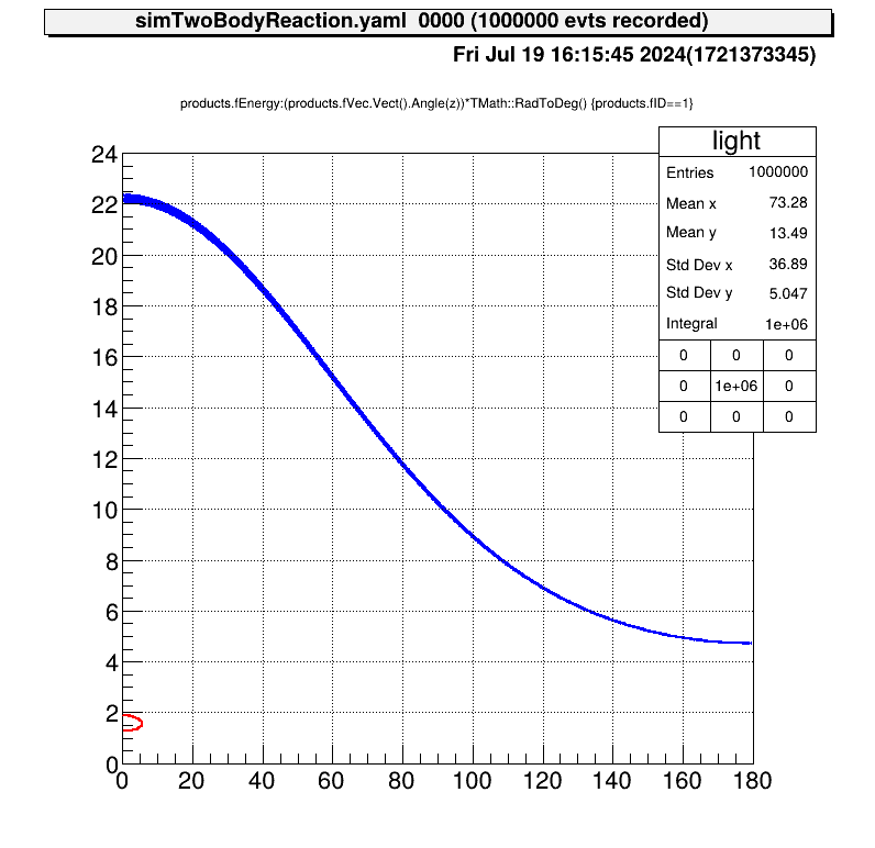
Details of the reactions that took place are shown in these figures.
The reaction cross section files are appropriately specified.
This figure is the reaction energy at CM system.
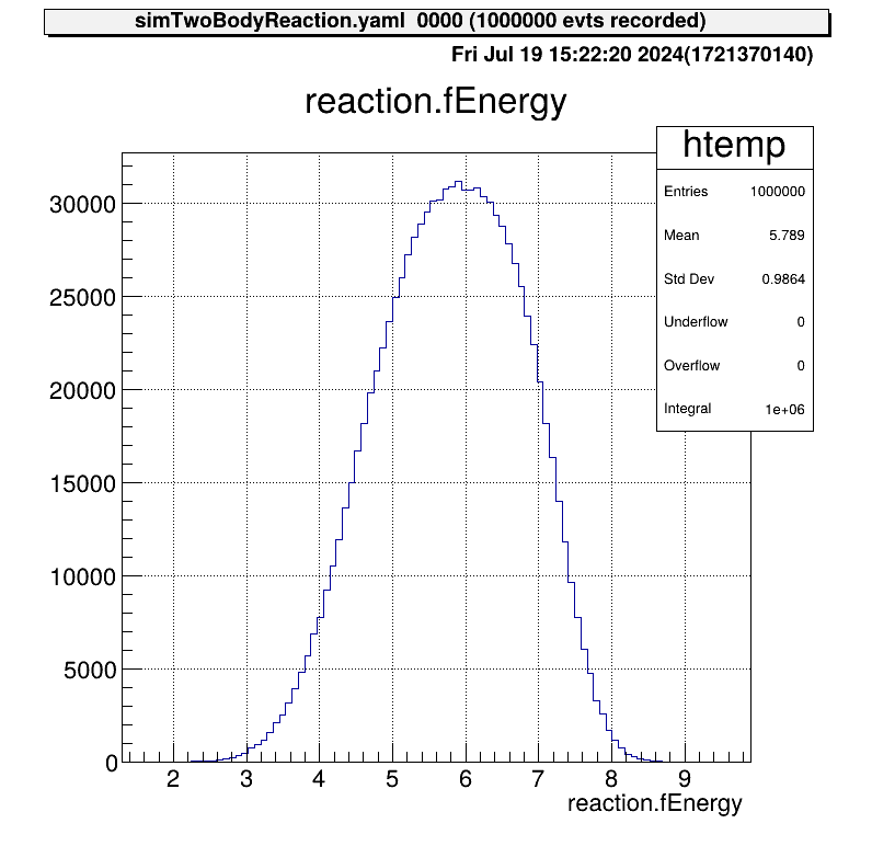
This distribution was created from a file of reaction cross section. The effect of beam energy spread is included, so the edge of the peak is not sharp.
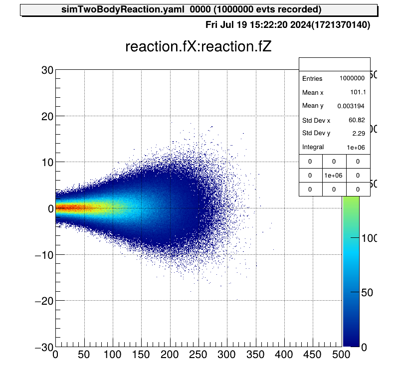
According to this energy distribution, the distribution of the positions of the reactions is as follows.
The angular distribution at CM system of reactions is assumed to be uniform. This figure shows the direction of one particle that is produced from this reaction.
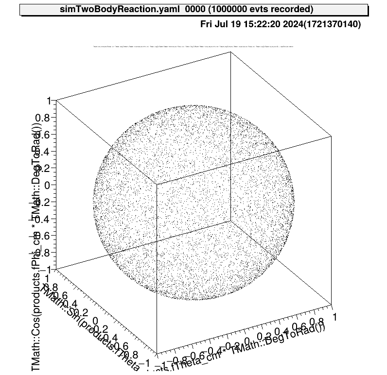
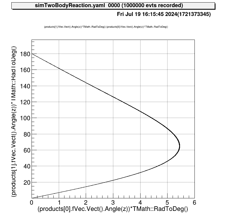
Also the relationship between the kinematics of the reactions will be like this.
