Preparation
This section explain the example of preparation by using some useful macro.
This section explain the example of preparation by using some useful macro.
I would now like to introduce the actual analysis using the CRIB analysis server. There are two ways to enter the analysis server, directly or remotely via ssh. If you come to CRIB and operate the server directly, I think it is quicker to analyse using the server while asking the CRIB members directly as I think they are nearby.
To enter the CRIB server, you need to enter the CNS network. To do this, you need to create an account on the CNS login server. Please contact Okawa (okawa@cns.s.u-tokyo.ac.jp) or the person responsible for CRIB (see here) and tell us that you want a login server account.
The CNS login server uses public key cryptography, so you need to send a shared key when you apply. This section describes how to create the key, especially on MacOS.
cd # move to /Users/yourname/ (home directory)
mkdir .ssh # if there is no .ssh directory
cd .ssh
ssh-keygen
You will be asked a number of interactive questions after this command, all of which are fine by default (Enter). Then you will see the pair of public-key and private-key.
ls
id_rsa  id_rsa.pub
id_rsa is the private-key, and id_rsa.pub is the public-key.
The private key is important for security reasons and should be kept on your own computer.
Then, please send this public-key to the CNS member.
in MacOS, open . command will open a finder for that directory, so it is easy to attach it to an email from here.
In the email,
are needed.
Next, let’s set up multi-stage ssh. As the login server is just a jump server, it is useful to be able to ssh to the CRIB analysis server at once! So create the following config file. The file placed in this directory is automatically read when you ssh.
cd ~/.ssh
vi config 1Host login
2 HostName CNS_loginserver_hostname
3 User username
4 IdentityFile ~/.ssh/id_rsa
5 ForWardX11Timeout 24h
6 ControlPersist 30m
7 ForwardAgent yes
8 ControlMaster auto
9 ControlPath ~/.ssh/mux-%r@%h:%p
10
11# any name is okay
12Host cribana
13 HostName analysisPC_hostname
14 User crib
15 IdentityFile ~/.ssh/id_rsa
16 ProxyCommand ssh login nc %h %p
17 ForwardAgent yes
18 ControlMaster auto
19 ControlPath ~/.ssh/mux-%r@%h:%p
20 ControlPersist 30mYou will be informed of the second and third lines above that we highlighted, so please change this parts. And ask the IP address of the CRIB analysis PC to the CRIB member, and change the 13 line.
Then you can enter the CRIB analysis PC just by
ssh cribanaCRIB member will tell you the passward!
For the VNC server (local forwarding), please see this section.
When you enter the CRIB computer, please check this is zsh shell.
> echo $SHELL
/usr/local/bin/zshCurrently, zsh installed locally is used. It is planned to update the OS in the future, after which it will differ from this path in the future.
If it is not zsh (like bash), please command
> zshThen you can start to configure by
> artlogin yourname
# input your information...

> mkdir build
> cd build
> cmake ..
> make -j4
> make install
> acd
For the detail, please check here.
> acd # move to your artemis work directory
> a # start artemis!

> a macro/macro.C # run macro script# read steering file
artemis [*] add steering/hoge.yaml NAME=hoge NUM=0000
# start event loop
artemis [*] res
artemis [*] start # defined in CRIB artemis
# stop event loop
artemis [*] sus
artemis [*] stop # defined in CRIB artemis
# help
artemis [*] help
# quit from artemis
artemis [*] .q# check and move the directory
artemis [*] ls
artemis [*] cd 0 # cd ID
# move to home directory in artemis
artemis [*] cd # cd .. will work?
# draw the histograms
artemis [*] ht 0 colz # ht ID option
artemis [*] hn colz # draw the next histogram object
artemis [*] hb colz # draw the previous histogram object
# divide the canvas
artemis [*] zone 2 2 # 2 x 2 canvas
# save and print the canvas
artemis [*] sa
artemis [*] pri# check the files
artemis [*] fls
# move to the created ROOT file
artemis [*] fcd 0 # fcd fileID
# check the all branches
artemis [*] br
# check the data members or methods
artemis [*] br branchname # ex. artemis [1] br ppaca
# the name of TTree object is "tree" (actually TArtTree object)
artemis [*] tree->Draw("ppaca.fY:ppaca.fX>>ppaca(100,-20.,20., 100,-20.,20.)","","colz")See here for an example using random numbers.
CRIB uses a multi-hit TDC called V1190 to take timing data (manual). When a trigger comes into this module, it opens a window with a set time width and records the timing of the data.
However, even if the signal is sent at exactly the same time to the trigger, due to the uncertainty in opening that window, the resulting channel will vary. Since absolute channel values will vary, but relative channel values for a given (especially trigger) timing will remain the same, it is necessary to subtract all data by some reference channel to achieve good timing resolution.
The signal that serves as the reference for that time is what we call Tref!
(Time reference)
Since it is essential that all events contain that data, we put the trigger signal in one of the channels and make it a Tref.
The “tref” settings are made in the following file:
Processor:
# J1 V1190A
  - name: proc_tref_v1190A_j1
    type: art::TTimeReferenceProcessor
    parameter:
      # [[device] [focus] [detector] [geo] [ch]]
      RefConfig: [12, 2,  7, 0, 15]
      SegConfig: [12, 2,  7, 0]
Parameters RefConfig and SegConfig are set using the same ID as in the map file.
The “RefConfig” represents the “Tref” signal and the “SegConfig” represents the V1190 module. Therefore, the role of the processor is to subtract the “Segconfig” V1190 all timing signal from the “RefConfig” tref signal.
To apply this processor, add the following line to the steering file. For example,
Anchor:
 - &input ridf/@NAME@@NUM@.ridf
 - &output output/chkf3@NAME@@NUM@.root
 - &histout output/chkf3@NAME@@NUM@.hist.root

Processor:
  - name: timer
    type: art::TTimerProcessor

  - name: ridf
    type: art::TRIDFEventStore
    parameter:
      OutputTransparency: 1
      InputFiles:
        - *input

  - name: mapper
    type: art::TMappingProcessor
    parameter:
      OutputTransparency: 1

  - include: tref.yaml
  - include: rf/rf.yaml
  - include: coin/coin.yaml
  - include: ppac/dlppac.yaml
  - include: ssd/f3ssd.yaml

  - name: outputtree
    type: art::TOutputTreeProcessor
    parameter:
      FileName:
- *outputThe tref.yaml should be written before the main processor. In this example, it is written right after TMappingProcessor, and we recommend writing it in this position.
CRIB use two kinds of PPAC (Parallel-Plate Avalanche Counter), charge division method or delay-readout method. The PPAC placed at the F1 focal plane is charge-devision type, and the parameters to be converted to position are fixed and do not need to be calibrated. Therefore we explain the calibration method for delay-line PPAC (dl-PPAC).
Here we briefly describe the principle of converting from the obtained signal to position, but for more details, see here1.
We will discuss the x-direction because x and y is exactly same. First, define the parameters as follows
The artemis codes calculate the X position like this formula (see TPPACProcessor.cc).
$$ X~\mathrm{[mm]} = k_x\left( \frac{T_{X1} - T_{X2} + T_{Xin-offset} - T_{Xout-offset}}{2} \right) - X_{offset}$$Check the sign carefully! We often mistook the direction!!
The $T_{X1},~T_{X2}$ are measured value by TDC, and $k_x$ and $T_{Xin-offset}$ are specific value to PPAC, so we need to care only $T_{Xout-offset}$ and $X_{offset}$. $X_{offset}$ value depends on where we put the PPAC, so what we have to do is determine the line calibration parameter ( $T_{Xout-offset}$).
The following is a list of dl-PPAC parameters used in CRIB experiment.
| PPAC ID | $k_x$ [mm/ns] | $k_y$ [mm/ns] | $T_{Xin-offset}$ | $T_{Yin-offset}$ |
|---|---|---|---|---|
| #2 | 1.256 | 1.256 | 0.29 mm | 0.18 mm |
| #3 | 1.264 | 1.253 | 0.22 mm | 0.30 mm |
| #7 | 1.240 | 1.242 | 0.92 ns | 1.58 ns |
| #8 | 1.241 | 1.233 | 0.17 ns | 0.11 ns |
| #9 | 1.257 | 1.257 | 0.05 mm | 0.04 mm |
| #10 | 1.257 | 1.257 | 0.05 mm | 0.04 mm |
Different units are used for the offset. However, since the effect of this offset is eventually absorbed to the other offset value, it is no problem to use the values if we calibrate it correctly.
PPAC parameters are defined in the following files
For example, it is like this:
Type: art::TPPACParameter
Contents:
# #7 PPAC
  f3bppac: # this is the name of PPAC, should be the same name with the one in steering file!
    ns2mm:
    - 1.240
    - 1.242
    delayoffset:
    - 0.92
    - 1.58
    linecalib:
    - 1.31
    - -1.00
    # 0: no exchange, 1: X -> Y, Y -> X
    exchange: 0
    # 0: no reflect, 1: X -> -X
    reflectx: 1
    geometry:
    - 0.0
    - 0.5
    - 322.0
    TXSumLimit:
    - -800.0
    - 2000.0
    TYSumLimit:
    - -800.0
    - 2000.0
ns2mm
This is $k_x$ and $k_y$ parameters -> input the fixed value
delayoffset
This is $T_{Xin-offset}$ and $T_{Yin-offset}$ parameters -> input the fixed value
linecalib
This is explained next.
exchange, reflectx
This parameter should be changed depending on the direction in which the PPAC is placed. The meanings of the parameters are given above as comments.
CRIB takes a coordinate system such that when viewed from downstream of the beam, the x-axis is rightward and the y-axis is upward. In other words, it takes a right-handed coordinate system with the beam as the Z-axis. While looking at the actual data, change these parameters so that the coordinate system becomes this coordinate system.
geometry
In the Line calibration, please set this value to (0,0). After Line calibration, if we put the PPAC with some geometry offset, we should change this parameters. Please be careful that the parameter will add minus this value for X and Y. Z offset will be used for TPPACTrackingProcessor.
TXSumLimit, TYSumLimit
Used to determine if it is a good event or not. Currently not used.
Before starting line calibration, please make sure that map file and steering file is correctly set. Also we need parameter file of prm/ppac/ch2ns.dat to convert TDC channel to ns unit. (already prepared I think)
graph LR;
    A[TDC channel] -->|prm/ppac/ch2ns.dat| B[ns scale]
    B --> |prm/ppac/dlppac.yaml|C{PPAC object}
When you complete the setting except for linecalib parameters, let’s start calibration!
We prepared two useful macros to calibrate dl-PPAC.
First, we have to prepare the data with masks on the PPAC like following picture. This mask has holes at 12.5 mm intervals.

The position of the alpha line through the central hole can be calculated and the offset adjusted to achieve that position. The geometry inside the PPAC is as follows. I think all PPAC geometries used by CRIB are the same.
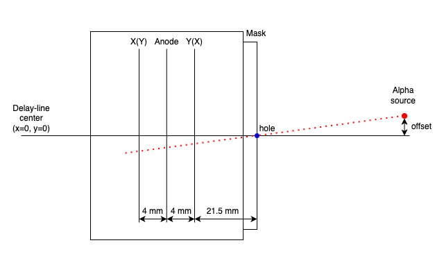
The parameters required to calculate the coordinates of the position are as follows.
Using these parameters, the macro/PPACLineCalibration.C calculate the theoretical position and how much the parameters should be moved.
Let’s calibrate PPACa as an example.
When we set the parameter like this files, the XY figure can be obtained.
Type: art::TPPACParameter
Contents:
  # #2 PPAC
  f3appac:
    ns2mm:
      - 1.256
      - 1.256
    delayoffset:
      - 0.29
      - 0.18
    linecalib:
      - 0.0
      - 0.0
    exchange: 0
    reflectx: 1
    geometry:
      - 0.0
      - 0.0
      - -677.0 # user defined
    TXSumLimit:
      - -800.0
      - 2000.0
    TYSumLimit:
      - -800.0
      - 2000.0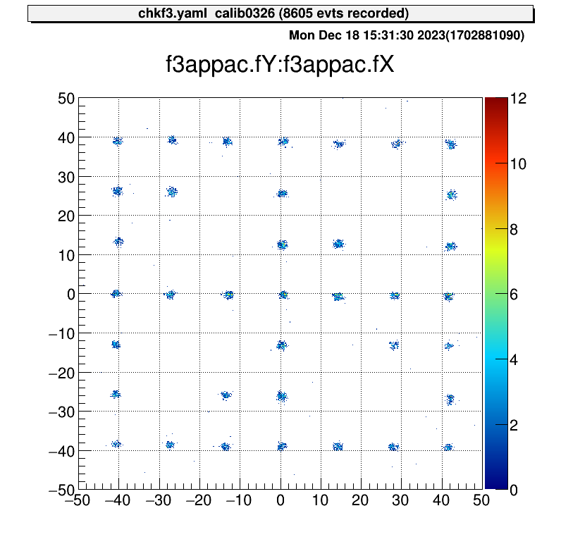
Then we can run the macro.
> acd
> vi macro/run_PPACLineCalibraion.C
# please set the parameters.
# instruction is written in this file

> a
artemis [0] add steering/hoge.yaml NAME=hoge NUM=0000
artemis [1] res
artemis [2] .x macro/run_PPACLineCalibration.C
# -- snip --

===================================================
center position (cal)  : (-0, -0.51413)
center position (data) : (0.890109, -0.274066)
difference             : (0.890109, 0.240065)
move parameters        : (-1.41737, 0.382269)
===================================================
And please input this value to the dlppac.yaml.
Type: art::TPPACParameter
Contents:
  # #2 PPAC
  f3appac:
    ns2mm:
      - 1.256
      - 1.256
    delayoffset:
      - 0.29
      - 0.18
    linecalib:
      - -1.417
      - 0.382
    exchange: 0
    reflectx: 1
    geometry:
      - 0.0
      - 0.0
      - -677.0 # user defined
    TXSumLimit:
      - -800.0
      - 2000.0
    TYSumLimit:
      - -800.0
      - 2000.0
Then you can complete the line calibration of the PPAC.
> a
artemis [0] add steering/hoge.yaml NAME=hoge NUM=0000
artemis [1] res
artemis [2] .x macro/run_PPACLineCalibration.C
# -- snip --

===================================================
center position (cal)  : (-0, -0.51413)
center position (data) : (-0.0191028, -0.571067)
difference             : (-0.0191028, -0.0569366) # <= almost zero!
move parameters        : (0.0304184, -0.0906633)
===================================================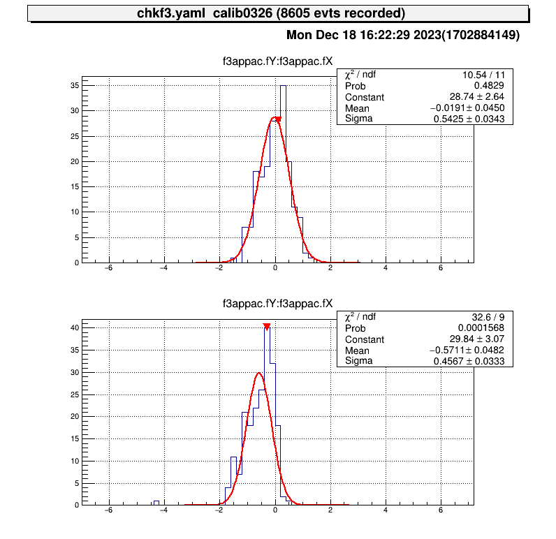
Because of the accuracy of the fitting, it does not make much sense to move the parameters any further.
The PPAC is then ready to be used by measuring how much offset the beamline axis has with respect to the delay-line axis at the position where the PPAC is actually placed, and putting this into the geometry parameters.
H. Kumagai et al., Nucl. Inst. and Meth. A 470, 562 (2001) ↩︎
updating…
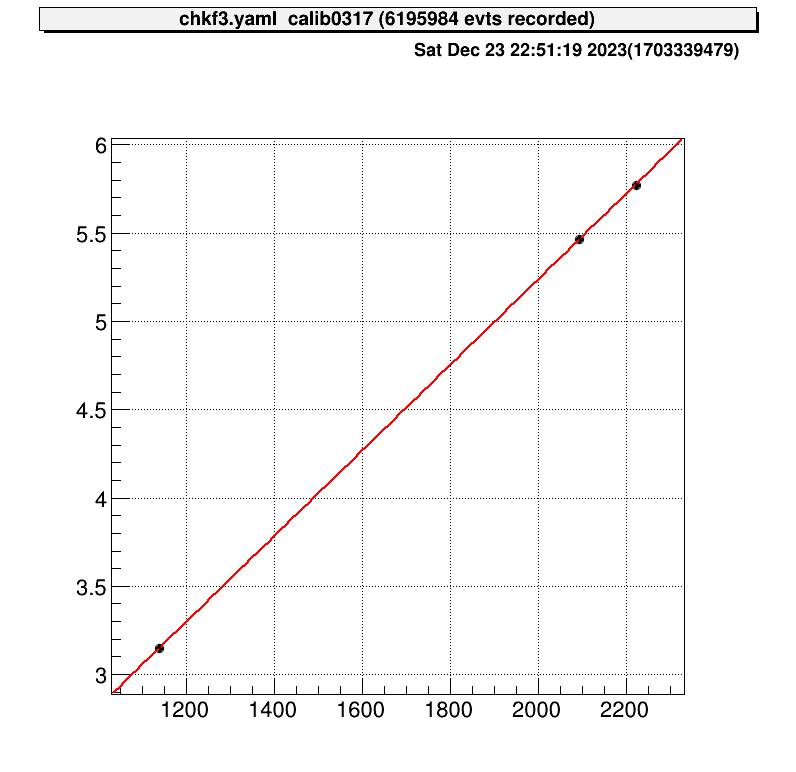
This is the CRIB alpha source information. (unit: MeV)
| ID | alpha-2 | alpha-3 |
|---|---|---|
| 4.780 | 3.148 | |
| 5.480 | 5.462 | |
| 5.795 | 5.771 |
SSD calibration files need to be set at prm/ssd/ directory.
The directory structure is like this:
$ tree -L 2 prm/ssd
prm/ssd
├── ch2MeV.dat # test file
├── ch2ns.dat # test file
├── f2ch2MeV.dat
├── f2ch2MeV_raw.dat
├── f2ch2ns.dat
├── tel1
│   ├── ch2MeV_dEX.dat
│   ├── ch2MeV_dEX_raw.dat
│   ├── ch2MeV_dEY.dat
│   ├── ch2MeV_dEY_raw.dat
│   ├── ch2MeV_E.dat
│   ├── ch2MeV_E_raw.dat
│   ├── ch2ns_dEX.dat
│   ├── ch2ns_dEY.dat
│   ├── ch2ns_E.dat
│   └── tel_conf.yaml # telescope configuration, explain later

-- snip --
The prm/ssd/ch2MeV.dat and prm/ssd/ch2ns.dat are used for test, so in the beam time measurement, actually this files are not necessory.
And prm/ssd/f2* files are used for F2SSD calibration, and files in prm/ssd/tel1/ directory are used for SSDs of a telescope.
The ch2ns.dat depends on TDC setting, so basically we don’t have to care so muc
(Usually the setting (the value) is same with previous experiment.), so we have to prepare the ch2MeV.dat files!
The file name need to be set like this example. The loaded parameter file name is defined SSD steering file, and we don’t want to change the SSD steering files so much, so please use such file names.
The “ch2MeV.dat” file format is like this:
# offset gain
1.7009  0.0173
0.0 1.0 # if there are some SSDs or strip SSD, you can add the line.We prepared useful macros to calibrate many SSDs. Please check these for more information.
It is sufficient to use the AlphaCalibration.C, but it is recommended to use the run_AlphaCalibration.C to keep a record of what arguments were used to calibrate.
After you prepared alpha calibration data and steering file (for example steering/calibration.yaml) to show raw data, you can use this macro.
$ acd
$ vi macro/run_AlphaCalibration.C
# please set the parameters.
# instraction is written in this file

$ a
artemis [0] add steering/hoge.yaml NAME=hoge NUM=0000
artemis [1] res
artemis [2] .x macro/run_AlphaCalibration.C
Then the parameter file that defined at the “run_AlphaCalibration.C” and calibration figures will be created automatically.
These are example of the figures;

$ a
artemis [0] add steering/hoge.yaml NAME=hoge NUM=0000
artemis [1] res
artemis [2] fcd 0
artemis [3] zo
artemis [4] tree->Draw("...") # draw calibrated data
artemis [5] gStyle->SetOptStat(0)
artemis [6] sa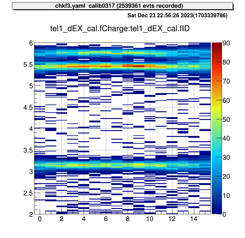
updating…
updating…
Analysis files for each experiment are managed using git.
This is so that they can be quickly restored if they are all lost for some reason.
Git is a bit complicated and you can commit freely if you are knowledgeable, but if you are unfamiliar with it, you don’t have to worry too much.
The main use is that if someone creates a useful file, it will be reflected for each user as well.
Here is a brief description of how to use it.
In the CRIB analysis PC, we used local repository. The files related the repository is stored here.
> cd ~
> tree -L 1 repos/exp
repos/exp
├── he6p2024.git
├── he6p.git
└── o14a.git

# 2023/12/18 current statusNote that if you delete the files in this directory, you will lose all backups.
I will describe the most commonly used commands and how to resolve conflicts.