PPAC calibration
last modified: 2023-12-18 by Kodai OkawaCRIB use two kinds of PPAC (Parallel-Plate Avalanche Counter), charge division method or delay-readout method. The PPAC placed at the F1 focal plane is charge-devision type, and the parameters to be converted to position are fixed and do not need to be calibrated. Therefore we explain the calibration method for delay-line PPAC (dl-PPAC).
Principles
Here we briefly describe the principle of converting from the obtained signal to position, but for more details, see here1.
We will discuss the x-direction because x and y is exactly same. First, define the parameters as follows
- $k_x$ : convert from signal time difference to position [mm/ns]
- $T_{X1},~T_{X2}$ : time at both ends of delay-line, measured at TDC [ns]
- $T_{Xin-offset}$ : timing offset come from inside the chamber [ns]
- $T_{Xout-offset}$ : timing offset come from outside the chamber [ns] (like from cabling)
- $X_{offset}$ : geometry offset [mm]
The artemis codes calculate the X position like this formula (see TPPACProcessor.cc).
$$ X~\mathrm{[mm]} = k_x\left( \frac{T_{X1} - T_{X2} + T_{Xin-offset} - T_{Xout-offset}}{2} \right) - X_{offset}$$Check the sign carefully! We often mistook the direction!!
Fixed parameters
The $T_{X1},~T_{X2}$ are measured value by TDC, and $k_x$ and $T_{Xin-offset}$ are specific value to PPAC, so we need to care only $T_{Xout-offset}$ and $X_{offset}$. $X_{offset}$ value depends on where we put the PPAC, so what we have to do is determine the line calibration parameter ( $T_{Xout-offset}$).
The following is a list of dl-PPAC parameters used in CRIB experiment.
| PPAC ID | $k_x$ [mm/ns] | $k_y$ [mm/ns] | $T_{Xin-offset}$ | $T_{Yin-offset}$ |
|---|---|---|---|---|
| #2 | 1.256 | 1.256 | 0.29 mm | 0.18 mm |
| #3 | 1.264 | 1.253 | 0.22 mm | 0.30 mm |
| #7 | 1.240 | 1.242 | 0.92 ns | 1.58 ns |
| #8 | 1.241 | 1.233 | 0.17 ns | 0.11 ns |
| #9 | 1.257 | 1.257 | 0.05 mm | 0.04 mm |
| #10 | 1.257 | 1.257 | 0.05 mm | 0.04 mm |
Different units are used for the offset. However, since the effect of this offset is eventually absorbed to the other offset value, it is no problem to use the values if we calibrate it correctly.
Parameter setting
PPAC parameters are defined in the following files
For example, it is like this:
Type: art::TPPACParameter
Contents:
# #7 PPAC
  f3bppac: # this is the name of PPAC, should be the same name with the one in steering file!
    ns2mm:
    - 1.240
    - 1.242
    delayoffset:
    - 0.92
    - 1.58
    linecalib:
    - 1.31
    - -1.00
    # 0: no exchange, 1: X -> Y, Y -> X
    exchange: 0
    # 0: no reflect, 1: X -> -X
    reflectx: 1
    geometry:
    - 0.0
    - 0.5
    - 322.0
    TXSumLimit:
    - -800.0
    - 2000.0
    TYSumLimit:
    - -800.0
- 2000.0-
ns2mm
This is $k_x$ and $k_y$ parameters -> input the fixed value
-
delayoffset
This is $T_{Xin-offset}$ and $T_{Yin-offset}$ parameters -> input the fixed value
-
linecalib
This is explained next.
-
exchange, reflectx
This parameter should be changed depending on the direction in which the PPAC is placed. The meanings of the parameters are given above as comments.
NoteCRIB takes a coordinate system such that when viewed from downstream of the beam, the x-axis is rightward and the y-axis is upward. In other words, it takes a right-handed coordinate system with the beam as the Z-axis. While looking at the actual data, change these parameters so that the coordinate system becomes this coordinate system.
-
geometry
In the Line calibration, please set this value to (0,0). After Line calibration, if we put the PPAC with some geometry offset, we should change this parameters. Please be careful that the parameter will add minus this value for X and Y. Z offset will be used for TPPACTrackingProcessor.
-
TXSumLimit, TYSumLimit
Used to determine if it is a good event or not. Currently not used.
Line calibration
Before starting line calibration, please make sure that map file and steering file is correctly set. Also we need parameter file of prm/ppac/ch2ns.dat to convert TDC channel to ns unit. (already prepared I think)
graph LR;
    A[TDC channel] -->|prm/ppac/ch2ns.dat| B[ns scale]
    B --> |prm/ppac/dlppac.yaml|C{PPAC object}
When you complete the setting except for linecalib parameters, let’s start calibration!
We prepared two useful macros to calibrate dl-PPAC.
- macro/run_PPACLineCalibration.C : Macro to actually execute
- macro/PPACLineCalibration.C : Macro that actually work
First, we have to prepare the data with masks on the PPAC like following picture. This mask has holes at 12.5 mm intervals.

The position of the alpha line through the central hole can be calculated and the offset adjusted to achieve that position. The geometry inside the PPAC is as follows. I think all PPAC geometries used by CRIB are the same.
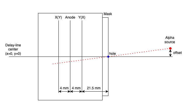
The parameters required to calculate the coordinates of the position are as follows.
- PPAC ID
- PPAC direction (first layer is X or Y)
- alpha source offset X
- alpha source offset Y
- distance between the mask and alpha source
- reflectx in the dlppac.yaml
Using these parameters, the macro/PPACLineCalibration.C calculate the theoretical position and how much the parameters should be moved.
Example
Let’s calibrate PPACa as an example.
- PPAC ID : #2
- First layer is Y
- alpha source offset X : 0.0 mm
- alpha source offset Y : 2.2 mm
- distance between the mask and alpha source : 92 mm
- reflectx : 1 (have reflection)
When we set the parameter like this files, the XY figure can be obtained.
Type: art::TPPACParameter
Contents:
  # #2 PPAC
  f3appac:
    ns2mm:
      - 1.256
      - 1.256
    delayoffset:
      - 0.29
      - 0.18
    linecalib:
      - 0.0
      - 0.0
    exchange: 0
    reflectx: 1
    geometry:
      - 0.0
      - 0.0
      - -677.0 # user defined
    TXSumLimit:
      - -800.0
      - 2000.0
    TYSumLimit:
      - -800.0
      - 2000.0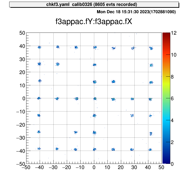
Then we can run the macro.
> acd
> vi macro/run_PPACLineCalibraion.C
# please set the parameters.
# instruction is written in this file
> a
artemis [0] add steering/hoge.yaml NAME=hoge NUM=0000
artemis [1] res
artemis [2] .x macro/run_PPACLineCalibration.C
# -- snip --
===================================================
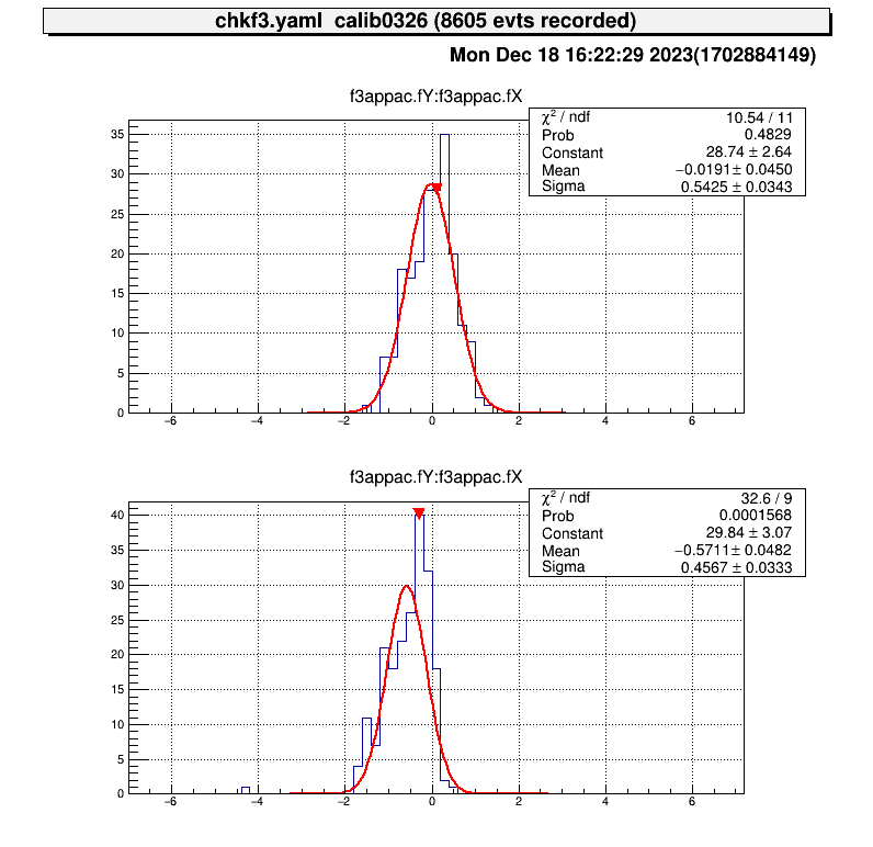
center position (cal) : (-0, -0.51413)
center position (data) : (0.890109, -0.274066)
difference : (0.890109, 0.240065)
move parameters : (-1.41737, 0.382269)
===================================================And please input this value to the dlppac.yaml.
Type: art::TPPACParameter
Contents:
  # #2 PPAC
  f3appac:
    ns2mm:
      - 1.256
      - 1.256
    delayoffset:
      - 0.29
      - 0.18
    linecalib:
      - -1.417
      - 0.382
    exchange: 0
    reflectx: 1
    geometry:
      - 0.0
      - 0.0
      - -677.0 # user defined
    TXSumLimit:
      - -800.0
      - 2000.0
    TYSumLimit:
      - -800.0
      - 2000.0
Then you can complete the line calibration of the PPAC.
> a
artemis [0] add steering/hoge.yaml NAME=hoge NUM=0000
artemis [1] res
artemis [2] .x macro/run_PPACLineCalibration.C
# -- snip --

===================================================
center position (cal)  : (-0, -0.51413)
center position (data) : (-0.0191028, -0.571067)
difference             : (-0.0191028, -0.0569366) # <= almost zero!
move parameters        : (0.0304184, -0.0906633)
===================================================
Because of the accuracy of the fitting, it does not make much sense to move the parameters any further.
The PPAC is then ready to be used by measuring how much offset the beamline axis has with respect to the delay-line axis at the position where the PPAC is actually placed, and putting this into the geometry parameters.
-
H. Kumagai et al., Nucl. Inst. and Meth. A 470, 562 (2001) ↩︎